
Microstrip antennas stand out to be distinct in all types of antennas having low cost, less weight, smaller size and easy to fabricate as per requirement. Moreover, Microstrip antennas also provide both forms of polarization that is Linear and Circular along with dual or single band of operating frequencies. Aforesaid features, make it to be the type being widely used in compact electronic devices and it also finds its wide application in various aircrafts applications. It has made great progress in recent years and played an important role in size reduction of electronic devices either in daily use items or essentially required aircraft equipment.
A typical Microstrip patch antenna is composed of a metallic strip on a dielectric substrate having a ground plane on the other side, purpose of which is to shield the circuitry from only one side but a normal Microstrip antenna can also have a second shield to reduce external interaction at a minimum level.Being planar in configuration, easy to fabricate and most suitable for integration, this type of antenna has been under great research and study.
Some of the major characteristics of a microstrip antenna as compared to other types are as under:
Microstrip Patch Antenna models differ in structure and configuration but generally, we have four basic segments which are described in succeeding paras
Conductive metallic part etched on upper surface of a substrate for radiation or absorption of electromagnetic waves is said to be Patch. Usually, it is made up of copper but can be other metals such as Silver as well. These can be designed in any geometrical shape like Rectangular, Square, Circular, Triangular, Elliptical, Circular Ring, Disc Sector or Ring Sector depending on the size, conformity and design consideration. Dimensions of this patch are important design parameters which help in achieving desired frequency ranges. Having various types of geometries, every kind has its own distinct features suitable for its specified application. Most common types of geometries being manufactured and used are rectangular and circular configuration due to ease of fabrication process and their analysis is also an easier process. Furthermore, Circular type has the symmetric radiation pattern which separates it from rectangular and other types of configurations.
Material on to which Radiation Patch is etched at upper side and Ground Plane at lower side is called as a Dielectric Substrate. These are available in a large variety with different dielectric constants (ϵr) which is an indication of relative permittivity of the material ranging from 2.2 to 12. Factors influencing the selection of substrate are its cost, dielectric constant and thickness. Since, substrate thickness is directly proportional to the frequency bandwidth, therefore a thick substrate with low dielectric constant is desirable for a wideband application which increases the antenna efficiency as well. Inexpensive glass epoxy substrate like FR-4 with ϵr = 4.3, is the most commonly used substrate for training or prototyping purposes.
Conductive material used for Ground Plane is similar to that of Patch and it is present at the lower side of the substrate. Antenna performance/ efficiency can be enhanced by increasing the size of ground plane but it is limited once optimum level of performance is achieved. Fringing field between Patch and Ground Plane generates the desired radiation pattern for antenna.
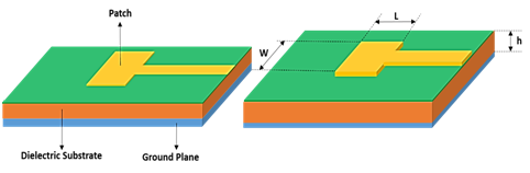
Figure 1: A typical Microstrip Patch Antenna
A number of feeding techniques exist but most commonly used are Microstrip Line, Coaxial Probe Feed, Aperture Coupling and Proximity Coupling. All of these are elaborated in succeeding paragraphs.
1) Microstrip Line
It is a type of feed in which a simple conducting strip is used to feed the patch. Though, it is easy to design and fabricate being only an extension of the patch and its position can be varied accordingly but it increases substrate height and spurious radiations which further lead to limited Bandwidth.
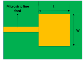
Figure 2 : Microstrip Feedline Patch Antenna
2) Coaxial Probe Feed
Inner conductor of Coaxial Probe is connected to the radiation patch of the antenna and outer conductor is connected to the ground plane of antenna. It is easy to design and fabricate with less thicker substrates. It has a low spurious radiation pattern but a relatively narrower bandwidth.
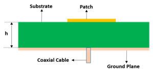
Figure 3: Coaxial Probe Feed Microstrip Patch Antenna
3) Aperture Feed
In this type of feed, two different types of substrates are used which are separated by a ground plane having a slot. There is a microstrip feed line on the bottom side of lower substrate, the feed of which is coupled to the patch of upper side through a slot present in the ground plane between two substrates. This provides the freedom of optimizing patch and feed independently for performance enhancement and design optimization. Normally, upper substrate is a thicker one having low dielectric constant whereas lower one is having a high dielectric constant. Ground plane present in the middle of both substrates separates the upper substrate from lower one thus isolating the feed from radiation which further minimizes the intrusion of spurious radiation, hence enhancing the polarization purity.
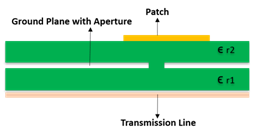
Figure 4: Aperture Feed Microstrip Patch Antenna
4) Proximity Coupling
This type of feeding mechanism also has two substrates of different dielectric constants. Radiating patch is present on the top surface of upper substrate and a microstrip line on the top surface of lower substrate which is connected to the power source. Lower substrate has a ground plane at its lower side. Greatest advantage of this type of feeding mechanism is its largest bandwidth, having less line/ spurious radiation as compared to microstrip line feed. However, its fabrication involves intricacies involving proper alignment of two substrates and multilayer fabrication. In this type of feed, matching is done by controlling the length of feeding strip line and width-to-length ratio of radiating patch.
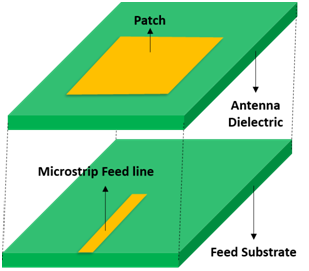
Figure 5: Proximity Coupled Microstrip Patch Antenna
Important Characteristics;
Range of frequencies over which an antenna operates correctly with all performance parameters in desired range is said to its Bandwidth. It may be only impedance or return loss bandwidth at times as specified. However, it is pertinent to note that there are several other definitions of bandwidth as well like directivity bandwidth, polarization bandwidth and efficiency bandwidth.
Antenna polarization is defined as the direction/ pattern of the waves transmitted or received by it. It can either be Linearly Polarized or Circularly Polarized. To know the exact type of polarization, axial ratio of antenna is to be measured which can be done in an anechoic chamber.
Power radiated from a microstrip element divided by the power received by it is called as Antenna efficiency. Total efficiency of the antenna depends on dielectric efficiency (ϵd), reflection efficiency (ϵr) and conduction efficiency (ϵc) and it is represented as:
ϵ = ϵd . ϵr . ϵc
As a matter of fact, Conduction efficiency and Dielectric efficiency are difficult to calculate so that total antenna efficiency is generally shown as
Efficiency = Power Radiated/ Power Received
Effective power transfer from the power source to the antenna is measured and called as Return Loss. It is the difference between power sent (Pin) towards the antenna and power returned back (Pr) from it.
Return Loss = 10 log10 (Pin / Pr)
Graphical representation of the radiation properties of an antenna as a function of space coordinates is said to be Radiation Pattern. There are different parts of a Radiation Pattern known as lobes. Each lobe has different radiation intensity with major lobe having the maximum value. A side lobe is the one, in a direction other than intended direction which may be adjacent to the main lobe. Similarly, a back lobe is the one adjacent but 1800 opposite to the main lobe.
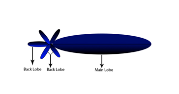
Figure 6: Lobes of a Radiation Pattern
Power radiated from an antenna per unit solid angle is radiation intensity.
It is the max power which an antenna can handle safely and operate normally with all operating parameters in normal range. Power handling capability is directly proportional to the range of antenna.
Ratio of voltage to current at the input port is said as Input Impedance. Both of these are distributed quantities of a transmission line and a function of their position on it. Impedance of the load must be equal to the impedance of source for transfer of max power from a source with fixed internal impedance to the load. For this reason, impedance matching is so important and normally an impedance of 50 is used while designing a transmission line. When impedance matching is done, maximum power transfer takes place between the source and a load.
Design and manufacturing process of an antenna involves certain steps which are mentioned as under:
Most essential parameters to be selected for design process are operating frequency, dielectric constant of the substrate and the height of dielectric constant. Making use of formulas and available data, certain calculations are made which give an overall idea of the dimensions of antenna to be designed for a specific frequency range. These dimensions are actual inputs of our software design along with desired frequency and dielectric constant.
All electromagnetic solvers are based on solving Maxwell equation in different forms. There are several softwares available for antenna desiging. Each has its pros and cons and most commonly used are IE3D, CST or Matlab. During software design stage, one can see all performance parameters of an antenna. Then, there are numerous techniques available in literature to control and bring the various parameters up to a desired level.
Finalized software design is exported out of the Antenna Designing Software in the form of a Gerber File. A milling machine is used to fabricate the antenna, in which rotary cutters are used to remove the copper from two layered board accurately as per dimensions of input file. Gerber files exported from antenna design software are input files for milling machine where the machine removes the copper and drills holes according to the input files.
Anechoic chamber allows the measurement of performance properties of antenna indoor by avoiding echoes/ reflections due to external interferences caused by metallic exterior. When a perfect prototype is ready then it is necessary to check its performance parameters in live operating conditions. A vector network analyzer is one of the most useful equipment used for antenna performance measurement. It is used to measure the Return Loss, Complex Impedance, VSWR, Gain and Insertion Loss. Antenna to be tested is connected to the port of Network Analyzer and is placed in Anechoic chamber. All the performance parameters can be seen, recorded and analyzed on Network Analyzer.
Popularity of Microstrip Antennas has improved to a great extent in recent past, mainly because of their thin planar configuration which can very easily be merged/ unified with surfaces of equipment like aircrafts and missiles without causing much of the drag. Ease of fabrication using printed circuit boards, ease of integrating the antenna on the same board with the rest of the circuitry and flexibility of adding devices to make these types as active antennas, thus make it a special and top priority choice for any Aircraft or Missile related application keeping in view the Aerodynamics involved therein.
Microstrip Patch Antennas having a circular polarization with substrate of high permittivity values are a favorite choice for Global Positioning System. These antennas are very compact in size and Millions of GPS receivers used by the general population for land/ vehicles navigation, aircraft, missiles and maritime vessels to calculate their own positions accurately are using these types of Antennas.
A small, low-cost and a low profile antenna is a perfect choice for any wireless application. Microstrip Patch Antennas fulfill the requirements of robust design for wireless communication and are widely being used both in Public Sector as well as for Aviation/ Aircrafts application. For satellite communication, circular polarization is achieved using either square or circular patch.
This system is a measures to increase cockpit awareness in modern aircraft vis-à-vis serve as a last defensive measure against any potential mid-air collisions between two aircrafts.
In the currently used worldwide configuration of this system, there are four monopole elements used as directional antennas and one blade type element is used as omni-directional antenna. But as a matter of fact, these existing antennas have some performance drawbacks like Lower Gain and Larger Beam width. Moreover, frequency tuning and beam scanning arealso certain issues being faced by operators. All these issues combined together may lead to a difficulty in recognizing a potential threat timely.
Keeping this in view along with most versatile characteristics of microstrip antenna, emphasis is now on the design of Microstrip Antennas which can be used for TCAS application. This type of antennas is expected to fulfill the requirements and standards of such like Avionics equipment in terms of design simplicity, lightweight and high performance.
With ever changing technology day by day, it is expected that an aircraft should be able to guard itself from any kind of risk or dangerous situation. Specially, military aircrafts are being designed with a view to defend themselves from any form of Electronic Attack.
To serve this purpose, antennas are essentially required to be frequency agile. A microstrip antenna, reconfigurable in nature can be made to have this important property by using multi-substrate layers, a cover layer and then placing it directly onto the surface of aircraft body. This would largely improve the impedance bandwidth of the microstrip antenna. Such type of antenna can be used for specific high performance aircraft applications.
Last but not the least, larger coverage angles can also be achieved by using arrays of microstrip antennas, installing on some curved surface having low profile. Such surfaces can be merged with shapes conforming to the airframe, wing and fuselage of the aircraft/ missile thus enhancing the use of these types of antennas for various applications. Singly curved surface can also be used as an approximation of the shape conforming to that of aircraft wing, fuselage or external pods. Such a design is expected to facilitate the use of microstrip antennas in defense applications including radar and communication systems avoiding the detection by adversary at the same time.
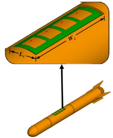

Figure 7: A Conformal Array of Microstrip Patch Antenna

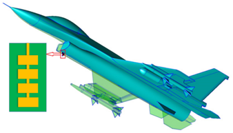
Figure 8: Microstrip Patch Antenna Array - Aircraft Application
 What Are Seaplanes And Their History Of Development ?
 Interesting Facts You Never Knew About Commercial Aircrafts And Aviation
 Extended Ground Proximity Warning System - EGPWS
 Airspace Classifications And The Air Traffic Control Services
 How An Instrument Landing System ( ILS ) Works
 EFB (Electronic Flight Bag)
 All About Aviation Fuels