The early day pilots didn’t have much of a choice on how to deal with this: in case of bad weather or conditions, they simply wouldn’t take-off and fly. But this was an issue that had to be solved.
During WWI, there was an urge to be able to take-off at any time, whatever the conditions; the war doesn’t wait for good weather. And after the war, when airmail services started being created, the same issue had to be solved.
Airplanes going faster and faster, flying higher and higher, being more and more technical, it was needed to fit them with something that could allow flying in a wider range of conditions.
First, they had radios, to get help from people on the ground; lights were fitted on the runways to be able to show them to the pilots during night or low visibility flights. For a few decades now, most airplanes that are allowed to fly IFR (Instrument Flight Rules) use all sorts of aids in order to land during bad conditions. We are going to talk about a very useful tool, the Instrument Landing System.
This system is quite self-explanatory; it is a system used to land using instruments (understand without visual information). It works by providing two information to the pilots when they are doing their final approach; indicating them the correct flight path to take to land correctly on the runway. This system uses radio waves, emitted on different frequencies that the plane can “hear” and with that know if it is in the correct position.
There are two different indications given by the ILS: a horizontal and a vertical indication. Let’s start with the horizontal one, the localizer. The localizer is an antenna situated at the far side of the runway, after it (the ILS system is designed for one specific approach direction of a given runway), and emit two different radio frequencies.
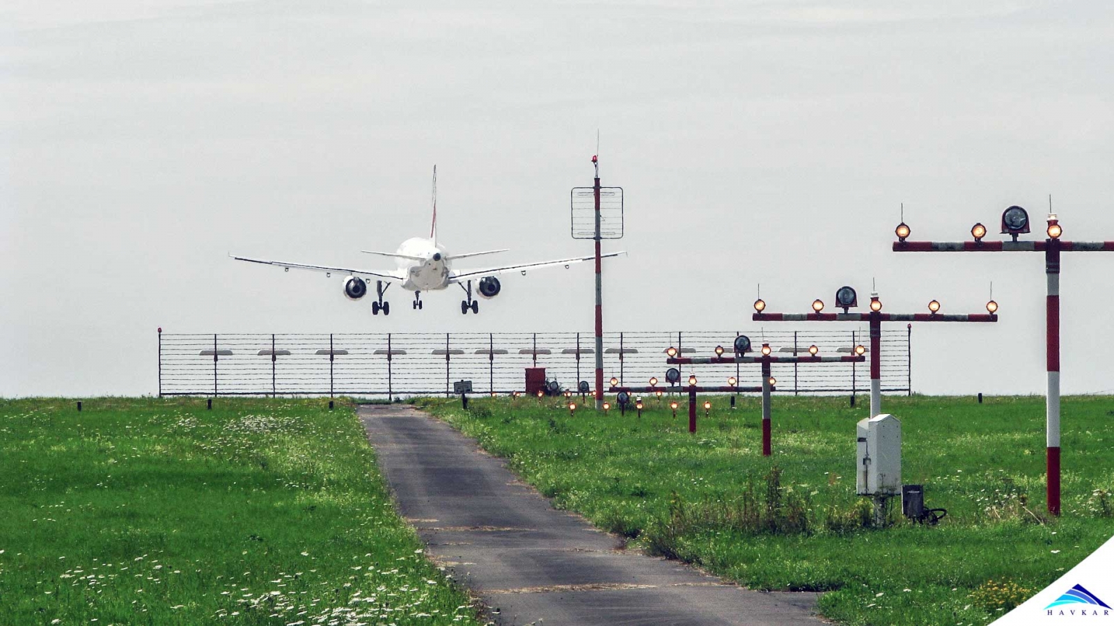
Here is a picture of a localizer antenna at the end of a runway.
This localizer emits two different radio frequencies, one to the left of the runway at 150Hz, and one to the right at 90Hz.
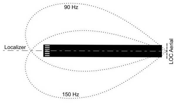
This is a drawing of the two signals emitted from the localizer, seen from above the runway.
By having two different signals, this allows the airplane approaching to know if it is correctly aligned: if the ILS instrument in the cockpit receives only a 90Hz signal, then the pilots know that they are too far to the left, and must head right.
The same thing happens, only in the opposite direction if the airplane only receives a 150Hz signal. The airplane is correctly aligned when it receives both a 150Hz and 90Hz signal, at the same intensity of course.
Now that we can be correctly aligned with the runway, we want to be able to land the airplane at the correct moment, without overshooting nor aiming too short on the runway. We use a second instrument called the glideslope for this.
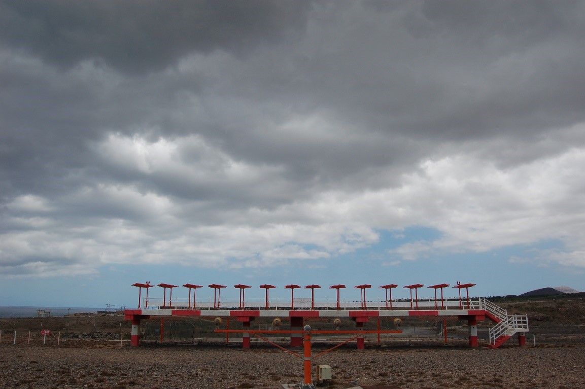
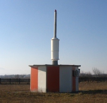
A glideslope at an airport. We can clearly see the difference with the localizer, the glideslope is a vertical antenna.
The glideslope works in a similar way as the localizer; emitting two different frequencies, allowing the airplane to know its position. The difference being that the waves are on a vertical plan. They are sent in order to make the plane to follow a 3° descent path. At least this is the most common angle, at some airport it can be different because of terrain, buildings, or any other obstacle. But 3° allows for the smoothest landing.
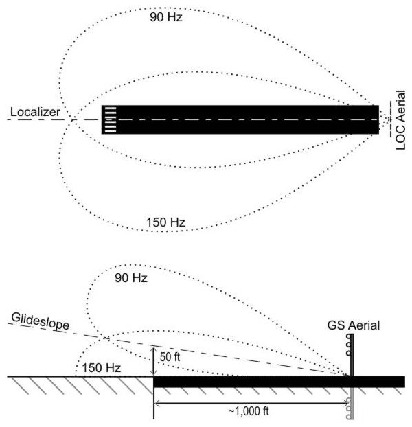
Here is a side representation of the signals emitted by the glideslope. We can see the path in between the 90Hz and 150Hz, at a 3° angle.
Finally, it is also important for the airplane to know its relative distance to the runway. Knowing how far from the runway the plane is, is also important information to have. Today we use DMEs to know that distance. DME stands for Distance Measuring Equipment, which basically is a radio wave emitting device, based on the transponder.
It calculates the time the waves make to go to the plane and come back. Knowing the speed at which the waves travel it is easy to have the distance at which the plane is situated.
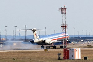
This is only an example of what a DME can look like, there are lots of different DME antennas.
These three components work all together to provide the sufficient information to the pilots, to allow them to safely land an airplane by night, fog, rain, or any low visibility conditions. This is a very useful tool that has greatly allowed improving the conditions this was something that allowed commercial airplanes to take-off nearly every day, at any time, but also is used in the military.
Military airplanes have to be able to take-off and land in pretty much any conditions, since a threat can come at any moment. These systems are thus also used on military aircraft and airfields, even if there are some differences with civilian systems. The DME for example is called a TACAN (TACtical Air Navigation system) in the military, even if it works in the same way, in a more accurate way.
Even if these systems are very helpful, they aren’t without limitations. Indeed, they are very useful for approaches that are done in a straight line, but some airfields do not allow for such landings.
There are some (more complicated, and so more expensive) systems that exist, allowing for non-linear approaches, but they are rather rare. Another problem is if the area before the runway isn’t flat, the waves can bounce on the ground and not give the correct path. Finally, ILS is a very expensive system, which requires some costly equipment, to install and also to maintain, so it is usually fitted only on the bigger airports.
 What Are Seaplanes And Their History Of Development ?
 Interesting Facts You Never Knew About Commercial Aircrafts And Aviation
 Extended Ground Proximity Warning System - EGPWS
 Airspace Classifications And The Air Traffic Control Services
 EFB (Electronic Flight Bag)
 All About Aviation Fuels
 What Is ADS-B ?