A wind turbine installation consists of the multiple sub systems linked together to harness the wind's energy, Converting wind power to rotational energy, convert mechanical rotation into electrical power, and other systems to start, stop, and control the turbine.
The Designing of such systems is done in multiple step process consist of up and forth analysis and study.
Here we are going to tell you how to do step by step CFD and perfect strategy to optimize the most efficient wind turbine.
There are two types of design of wind turbines based on the rotational axis alignment.
1.Horizontal Axis Wind Turbines 2. Vertical Axis Wind Turbines.
We will consider the horizontal Axis Turbine for the design analysis as these are the widely used wind turbine for wind farm use.
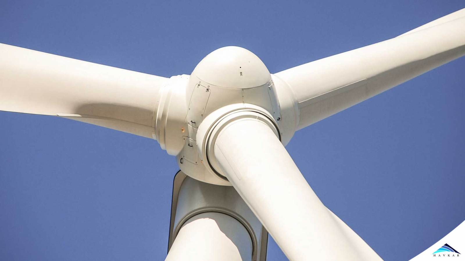
Since A wind turbine has any parts and section to convert wind energy into Electrical Energy we are going to focus on the rotor design and its blade as the wind flow is going to effect this section only. Which can be easily studied by the CFD (Computational Fluid Dynamic)?
Rotor of a wind turbine consists of Blades and hub. The design parameters for the blades and the rotor make lot of difference in the efficiency of the wind to electric energy conversion. This is the part of aerodynamics which plays a vital role in more efficiently extracting of wind energy. Since Air flow on the rotor blades is not same along all the height of the blade as the airflow over tip of the blade is different from the root of the blade.
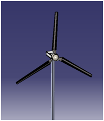
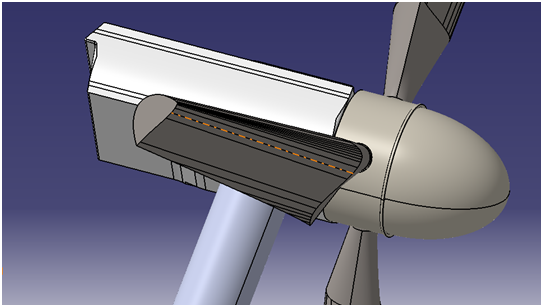
Wind Turbine Cad Model.
Also consider that the rotational speed (in RPM) of the rotor makes the airflow to move fast at the tip while at slow speed on the root section of the blade. So these are the parameters which can be optimized by use of CFD.
Let’s discuss these in details.
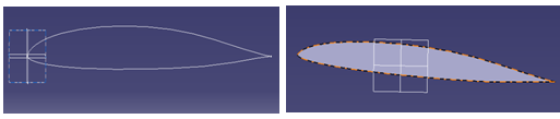
E231(thick) vs E374(Medium thickness) Airfoil.
To make the right selection of Airfoil 2D CFD analysis is proffered on all of them which you think can perform well then compare each other for the Cl vs Cd values. The CFD is done on the standard Operating wind speed at various angle of attack. It can be done in steps of 0,5,10,15 degrees or also the variation of speed can be considered which makes the whole analysis long but it gives more accurate results. For Example:
CFD of Airfoil.
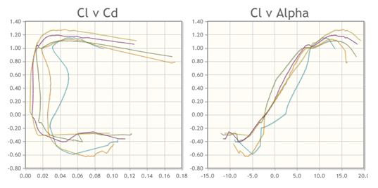
Graph Plotted between Cl vs Cd and Cl vs Angle of attack.
Based on these results one can easily compare and choose the best airfoil their optimum wind speed.
Cross Section at the tip and variation of Angle of attack across lade length.
The reason is pretty simple when it comes to wind turbine producing electrical energy more rotational speed of rotor is required while the torque is secondary. But during old turbines the requirement was to the more torque to rotate those heavy water pump or grinding mills. So the rotation speed of rotor was secondary choice. The number of blades showcases the relation between rotational speed of the turbine rotor, and torque which is produced by the rotor, so the finest speed the rotor can turn to generate maximum power. But now the question arises why not we use 4 or 5 bladed profile. Its answer is in the minimum torque required to rotate the generator also to keep the minimum RPM of the turbine at same time. Which depends on the minimum wind velocity available at particular location and designing the blade as per that particular wind velocity so each blade cover the maximum area without creating blackout area(without air) for the next blade rotating behind the first one. That is called the stall. Stall can be created by increasing angle of attack to a limit that the flow start separating on the blade or by having more number of blade which leads to surge of the flow.
Choosing between 3 or 5 blades can be done by CFD easily. Create as more models as the number of blades you wish to have in a rotor and with the selected profile. Solve it for the operational wind speed and rotational velocity. Find the parameters like Cl(Coefficient of lift) Cd(Coefficient of Drag) And Cm(Coefficient of Moment) which can help to find the produced torque and can be compared in between 3, 4 or 5 bladed models to find the best one.
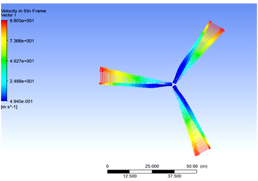
3 Bladed Rotor CFD
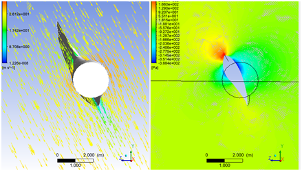
Airflow Across rotor hub and over the cross sectional plane.
After done with all these stages no one knows which airfoil, number of blades and rotor diameter to be used for the final designing of full scale cad model of his wind turbine and then under those optimum boundary conditions we assumed during above analysis, same can be used on the 3D full scale model. Final CFD is done on the same rotational speed and the wind speed.
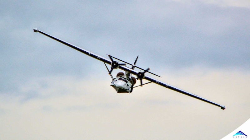 What Are Seaplanes And Their History Of Development ?
 Interesting Facts You Never Knew About Commercial Aircrafts And Aviation
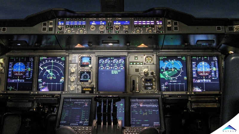 Extended Ground Proximity Warning System - EGPWS
 Airspace Classifications And The Air Traffic Control Services
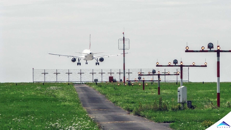 How An Instrument Landing System ( ILS ) Works
 EFB (Electronic Flight Bag)
 All About Aviation Fuels