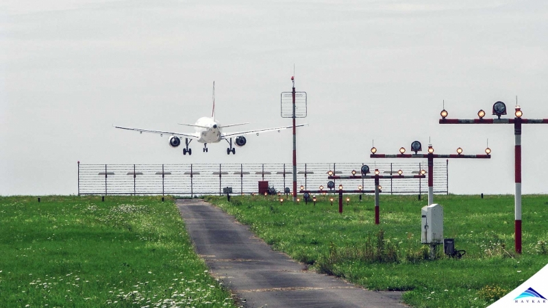
The two airplanes below are: first, the Embraer E190 and second, the Embraer E190-E2. The E190 was introduced in 2004 while the E190-E2 will start its operations in 2018.
Figure 1 – Embraer E-190
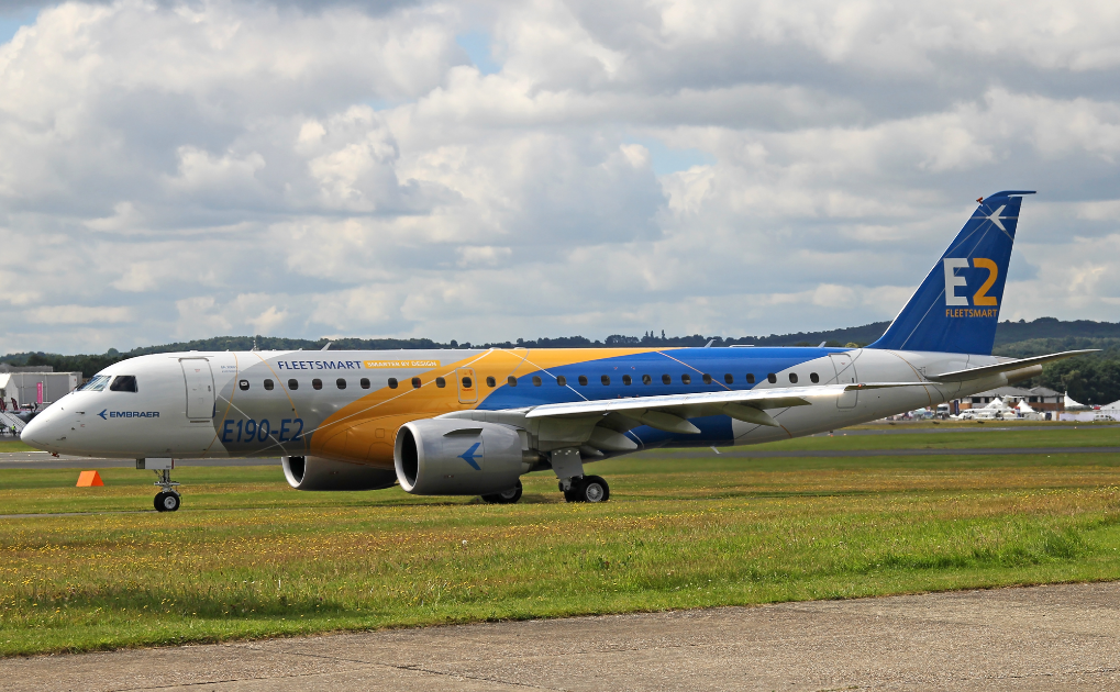
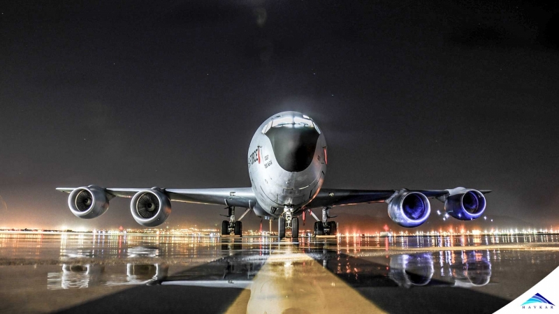
Figure 2 – Embraer E190-E2
The table below shows a comparison between some of their specifications.
|
|
E190 |
E190-E2 |
|
MTOW [kg] |
51,800 |
56,400 |
|
Max. Installed Thrust [kN] |
90.6 |
102.3 |
|
Wingspan [m] |
28.72 |
33.7 |
|
Length [m] |
36.2 |
36.2 |
|
Maximum single class seats |
114 |
114 |
|
Engine Model |
General Electric CF34-10E |
Pratt & Whitney PW1900G |
|
Engine Weight [kg] |
1700 |
2177 |
Table 1 – E190 and E190-E2 Comparison
They are in the same category of maximum takeoff weight (MTOW) and installed thrust. Also, they are very close in length and wingspan, considering the E190 has winglets and the E190-E2 does not.
Refer to Figures 1 and 2, compare the individual proportions of the two aircraft for a moment and try to spot one of the main differences between them. Do not focus on tiny details, but rather on that difference that really gets your attention. Did you notice how large the engines on the E190-E2 look?
The turbofan engines on the E190 have a diameter of 1.40 m while the ones equipping the E190-E2 have 1.85 m in diameter. Whywould Embraer decide to equip its new regional jet with a 32% larger, 28% heavier engine, if it produces only about 10% more thrust than the old one?
Jet Engine Basics:
To answer the previous question, it is necessary to have a little understanding on how a jet engine works. A jet engine, whether it is a pure turbojet or a turbofan provides thrust by ingesting the intake air and exhausting it in a higher speed to the atmosphere. Regarding jet engines, it is reasonable to state, as a good approximation:
the thrust produced is equal to the product of the mass flow rate of air through the engine and the increase in velocity the stream of air has gained while passing through the engine.
In Another Notation:
![]()
(1)
Where:
![]() is the thrust produced by the engine
is the thrust produced by the engine
![]() is the air mass flow rate through the engine
is the air mass flow rate through the engine
![]() is the increase in velocity of the air stream passing through the engine
is the increase in velocity of the air stream passing through the engine
With that in mind, the inspection of Equation 1 leads to the conclusion that, in order to increase thrust from a given baseline, two things can be pursued:
1) Increase the air mass flow rate through the engine;
2) Increase the amount of acceleration given to the air stream that goes through the engine.
Another interesting way to analyze it: to maintain the same amount of thrust, air mass flow rate can be increased while air stream acceleration is proportionally decreased, and vice-versa.
With the information above, observing again that the engine diameter of the E190-E2 is larger than the one used on E190, and considering that they produce similar values of thrust, we can conclude that:
a) the air mass flow rate has been increased (larger inlet, more air coming in) and, thus,
b) the amount of acceleration given to the air stream has been decreased.
Why was this done? The answer: fuel efficiency.
More Jet Engine Basics:
One way the fuel efficiency of an engine can be evaluated is through a parameter called propulsive efficiency. A larger propulsive efficiency means a smaller fuel burn. The propulsive efficiency for a jet engine of an aircraft is defined as:
![]()
(2)
Where:
![]() is the thrust produced by the engine
is the thrust produced by the engine
![]() is the free stream velocity of the aircraft
is the free stream velocity of the aircraft
![]() is the input power provided by the fuel burn to the run the engine
is the input power provided by the fuel burn to the run the engine
to the aircraft by the engines to fly at a speed equal to ![]() . This way, the propulsive efficiency in Equation 2 gives how much of the useful power produced by the engines is used to actually move the aircraft.
. This way, the propulsive efficiency in Equation 2 gives how much of the useful power produced by the engines is used to actually move the aircraft.
After a few manipulation steps (see Reference 1), Equation 2 becomes:
(3)
From Equation 3, it is clear that propulsive efficiency is roughly inversely proportional to air stream acceleration ![]() and, in conjunction with Equation 1, it is possible to conclude that propulsive efficiency increases with air mass flow rate, if thrust is to be maintained constant.
and, in conjunction with Equation 1, it is possible to conclude that propulsive efficiency increases with air mass flow rate, if thrust is to be maintained constant.
Should engines be made larger and larger, then?
If, to provide the same amount of thrust, increasing the air mass flow rate while decreasing the increment in the air stream velocity gives a reduction in fuel consumption, then engine designers and manufacturers should make them as large as possible, shouldn’t them? Well, it is not that simple.
One problem of making an engine larger is that, even though it could be more efficient, it may not be suitable to be installed on an actual aircraft. Or, in order to do so, the landing gears would have to be very long to provide minimum clearance of the engine from the ground, in low wing aircraft. This could increase weight and complexity and even make the design unfeasible. Moreover, a larger engine is intrinsically heavier and the additional weight in the aircraft design may not compensate the amount of fuel it will save.
Besides all of those considerations, the main problem with increasing engine size is the formation of shock waves in the tips of the fan blades. When the fan rotates, its tip has a higher tangential velocity than its root. As the tip speed reaches the speed of sound, shock waves are formed at the region, which drastically reduces the engine efficiency. The only way to increase the fan diameter while not making the Mach number at its tip higher is to reduce its rotational speed. This is exactly what has been made in the design of the PW1900G, which equips the E190-E2.
How to reduce fan speed, increase its size and, then, burn less fuel
Both the Embraer E190 and E190-E2 use turbofan engines. As explained in the article, “How does a turbofan engine work”, for this kind of engine, the total exhausted air is composed by the hot stream that goes into the engine core and leaves the turbine, plus the cooler stream that goes only through the outer areas of the fan and passes outside the core on its way to exhaustion.
Typically, the fan is directly driven by the low-pressure turbine and, thus, they both spin with the same high rotational speed of the turbine. This is how the CF34-10E used on the E190 works. However, for the PW1900G installed on the E190-E2, a design feature makes all the difference: a gearbox connecting the low-pressure turbine to the fan.
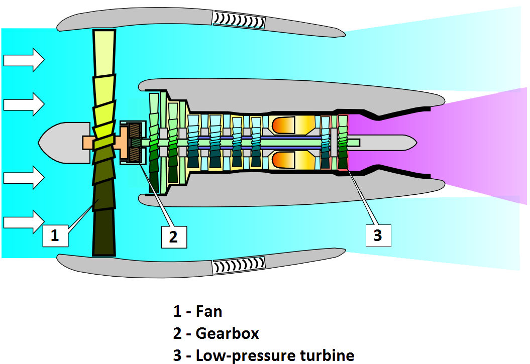
Figure 3 – A geared turbofan, such as the PW1900G
The engine depicted on Figure 3 is usually called a geared turbofan. The gearbox connects the low-pressure turbine, which rotates at very high speeds, to the fan. The gearbox transfers the power from the turbine while providing a much lower rotational speed to the fan. This way, it can be designed with a larger diameter before shock waves start to appear. With a larger diameter, there is an increase in air mass flow rate, which makes possible a reduction in the acceleration of air flow through the engine, while maintaining the same produced thrust. This way, a higher propulsive efficiency is achieved, leading, ultimately, to reduce fuel burn.
The addition of a gearbox definitely adds complexity to the design and manufacturing of the engine. Also, it can increase the weight of the power plant. However, when designed taking into consideration all of those variables, the net result can be positive. It seems that this has been the case for the PW1900G. According to Embraer (check Reference 2), the E190-E2 consumes 16% less fuel per seat when comparing to the E190. Even though the full fly-by-wire flight control system and the new wing design surely give their contribution to this increased efficiency, the reduction in fuel consumption owns mostly to the new geared turbofan engines.
Wrap Up
One thought after comparing the size of the engines on the E190 and the E190-E2 could easily be that the biggest power plant consumes more fuel. However, the way turbofan engines work leads to the inverse result. The addition of a gearbox connecting the low-pressure turbine to the fan makes feasible the increase in engine diameter, leading, ultimately, to better fuel efficiency. In the case of the Embraer jets, double-digit savings in fuel-per-seat.
References:
1. PHILLIPS, W. F. – Mechanics of Flight, 2nd Edition. Wiley. Hoboken, New Jersey. 2010.
 What Are Seaplanes And Their History Of Development ?
 Interesting Facts You Never Knew About Commercial Aircrafts And Aviation
 Extended Ground Proximity Warning System - EGPWS
 Airspace Classifications And The Air Traffic Control Services
 How An Instrument Landing System ( ILS ) Works
 EFB (Electronic Flight Bag)
 All About Aviation Fuels